

Building a Ghostbusters II KUD Meter.

The KUD meter is an interesting piece of Ghostbusters’ tech. It sits between the real-life objects slyly used on screen, like the Monitor 4 and Radica meters, Realistic sound level meter, or the Bacharach Sniffer, and the fully custom props like the PKE Meter and the Giga meter–both coincidentally built on the body of an electric scrubber. The KUD, or Kitchen Utensil Detector as named by fan Brent Kling, is a custom prop that doesn’t function on screen but is made of parts that are not modified, or only lightly modified. It consists of an old Radio Shack metal detector, a potato masher, a kitchen strainer, and one LED light. At no point do we see the light turn on, the needle on the screen move, or hear any sound. But it isn’t a real piece of tech they hoped you wouldn’t look at too closely; it was clearly built to look like in-universe, custom-made Ghostbusting equipment.
I think that's why it doesn’t have a lot of fans. It isn’t a cool piece of vintage tech, and it isn’t a complicated prop that we see function. On top of that, it appears only once in Ghostbusters II, and it's clearly built from a kitchen strainer. It just lacks that cool factor for most people. Not me; I am not one of those people, because I love everything about Ghostbusters II. Learning it uses a Radio-Shack metal detector from the 70s, plus a couple of kitchen utensils, kept me fascinated.
Let’s Make a “Functioning” KUD Meter
When I finally decided to do this, I had seen people over the years make versions of this prop with a blinking LED, a functioning readout, and other little touches like sounds and backlights. I wondered what I could add to my build to make it “function” without taking too much away from the original prop as seen in the film.
So I decided to add an EMF detector inside.
The finished KUD meter using "room scan"
If you don’t know, an EMF detector is a piece of technology used to detect levels of Electromagnetic Fields in any given space. It's not necessarily obsolete, but the wiring and electronics in our homes and infrastructure are much better shielded these days. If you’ve heard of an EMF detector at all, it is probably related to ghost hunting. The theory is that ghosts and spirits exist in a way that they are either composed of, or manipulate, the electrons in our plane of existence. Thus, you can detect major changes in the electromagnetic field around us. So that seemed like a great addition to a Ghostbusters prop build. Hasbro did the same thing recently with their Afterlife-inspired PKE meter. I have an old Dr. Gauss brand EMF detector that I used in a past life for my own ghost-hunting hobby, and it's a great candidate.
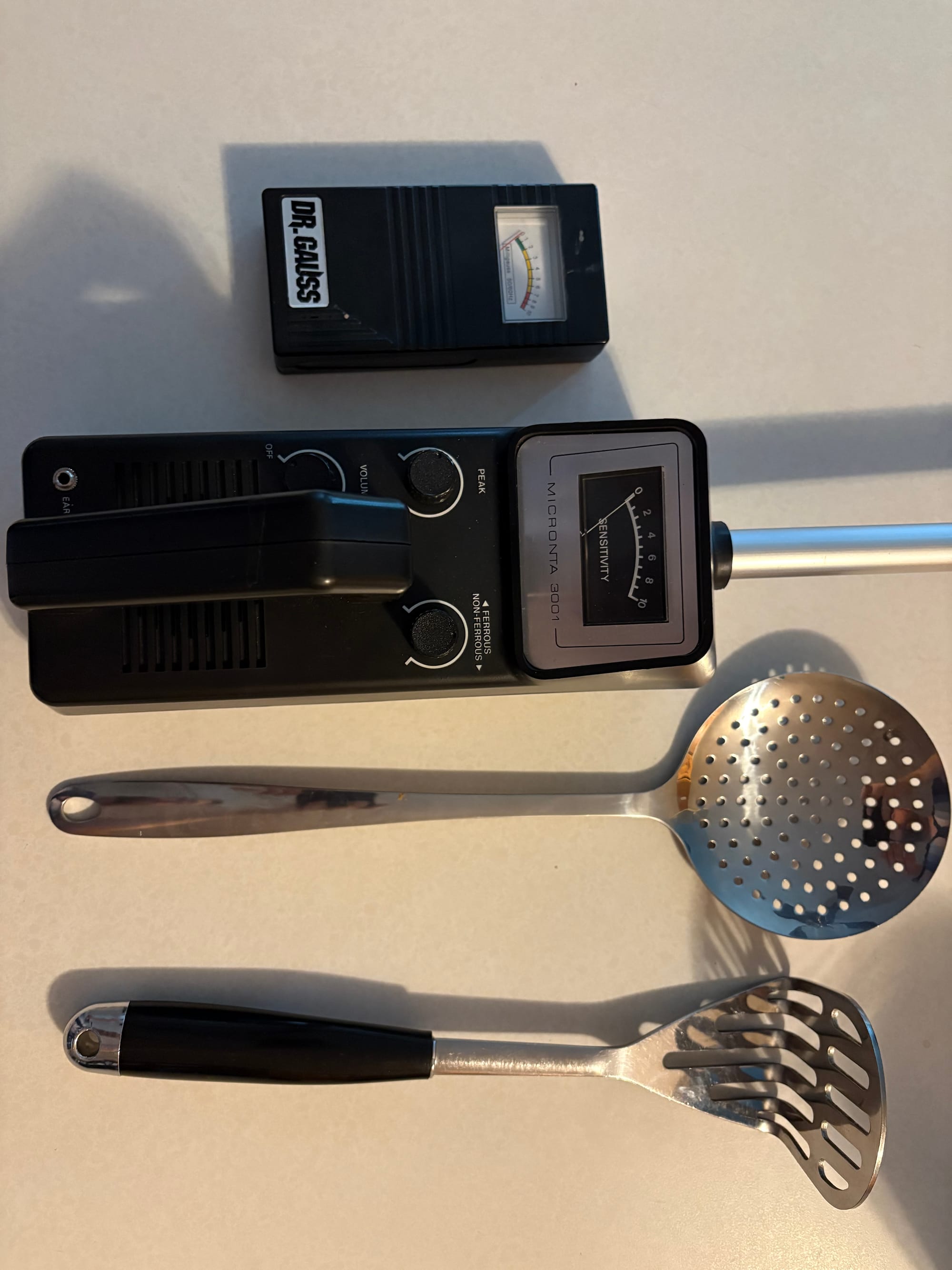
Parts List
- A Radio-Shack Micronata 3001 Metal Detector (A 4001 model will also work but is not the same)
- A Potato/Vegetable Masher*
- A kitchen strainer/skimmer**
- 1 Red LED
- Some wiring for some soldering work
- Solder gun, solder & flux
- Double-sided tape for mounting the EMF detector board
- Electrical tape
- Heat-Shrink tubing
- M8 hex screws, washers and nuts.
- One push-button switch***
- EMF Detector****
*You can use any masher you want, I don’t think the screen accurate one has ever been identified and it is unlikely to be still made anyway. I went with a Michael Graves Designs Vegetable Masher. You will find these on eBay.
** Same applies here. You want something with a good spread of small holes. I grabbed a Farberware Professional Stainless Steel Skimmer. https://www.amazon.com/dp/B0085U3TOQ
***I wanted this to be discreet and it needed to function in the same way as the EMF detector which is a single press to turn on and a hold to do a “room scan”. So a toggle you might see on a piece of GB tech wouldn’t work for me; you can switch this out depending on the kind of EMF detector you choose (if you do at all). I will likely replace my switch with something like this eventually https://www.amazon.com/dp/B083JWJPW5
****I had a Dr. Gauss EMF detector lying around; you can still find these. Sometimes they are also called Gauss Master. They're no longer made, so there might not be many out there. You can go with any EMF detector, but the instructions for that part won’t be exact, though I’m sure there is some crossover. These aren’t complicated devices, and they all tend to work the same.
The Disassembly
Taking your metal detector apart is easy. Two screws in the back hold it together on top, and a longer screw under the battery cover, a sticker covered mine, holds it together on the bottom (as well as the handle). The top part of the handle is held on by a longer screw on the inside that also holds the rod in place. At the top, a bracket goes across the rod and is held on with two short screws; remove that, too. Then snip off the curly cord coming down the inside of the rod and connected at the bottom of the board, and remove the whole rod. Then remove the big puck at the top of the rod and the smaller extension rod, pull the cord out, and you’re done. We only need the large main rod, so everything else is trash or treasure for a later project.
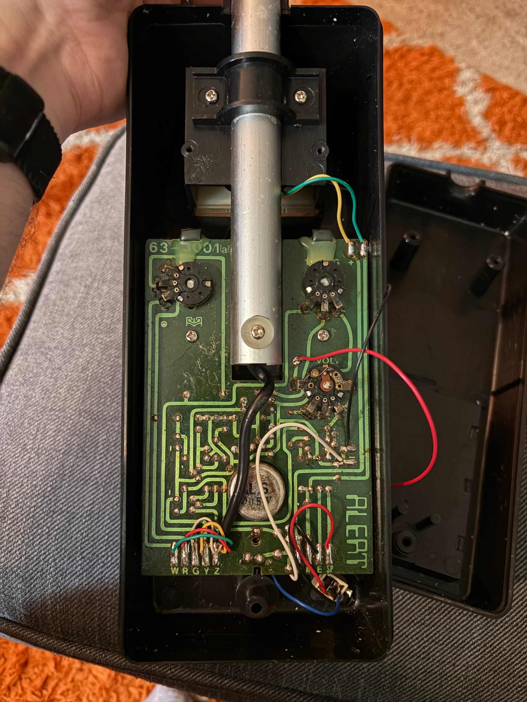
Now we’re going to snip a few wires. Cut the yellow and green wires coming from the screen to the board. We'll use them again, so snip them close to the board. Then cut the red and black wires to the battery compartment; we don’t need these again.
The Dr. Gauss EMF detector had four screws on the back. Once you open it, the large side button falls off, and everything else is one unit. Snip off the readout screen, but leave some good connection points; we’ll be using those. We'll also be using the 9V battery connector and the little speaker again, but we’ll need to extend them. Cut them now and mark them, or wait until later- your call.
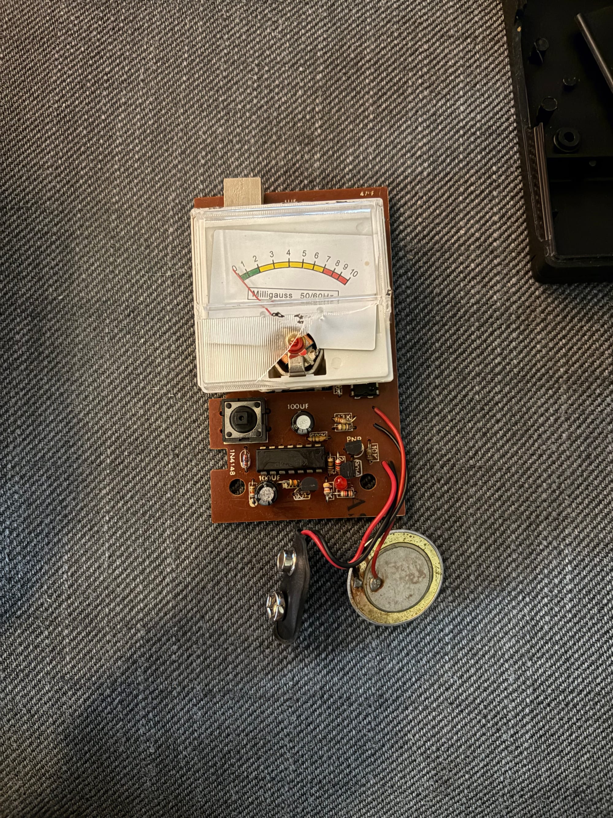
I was very excited to find a tiny red LED light inside this thing. I have no idea why it's in there, and you can't see it, but it made this build so much easier. Now, instead of attaching an LED to its own circuit with its own capacitor, I can daisy-chain it onto the current LED and run it outside the case.
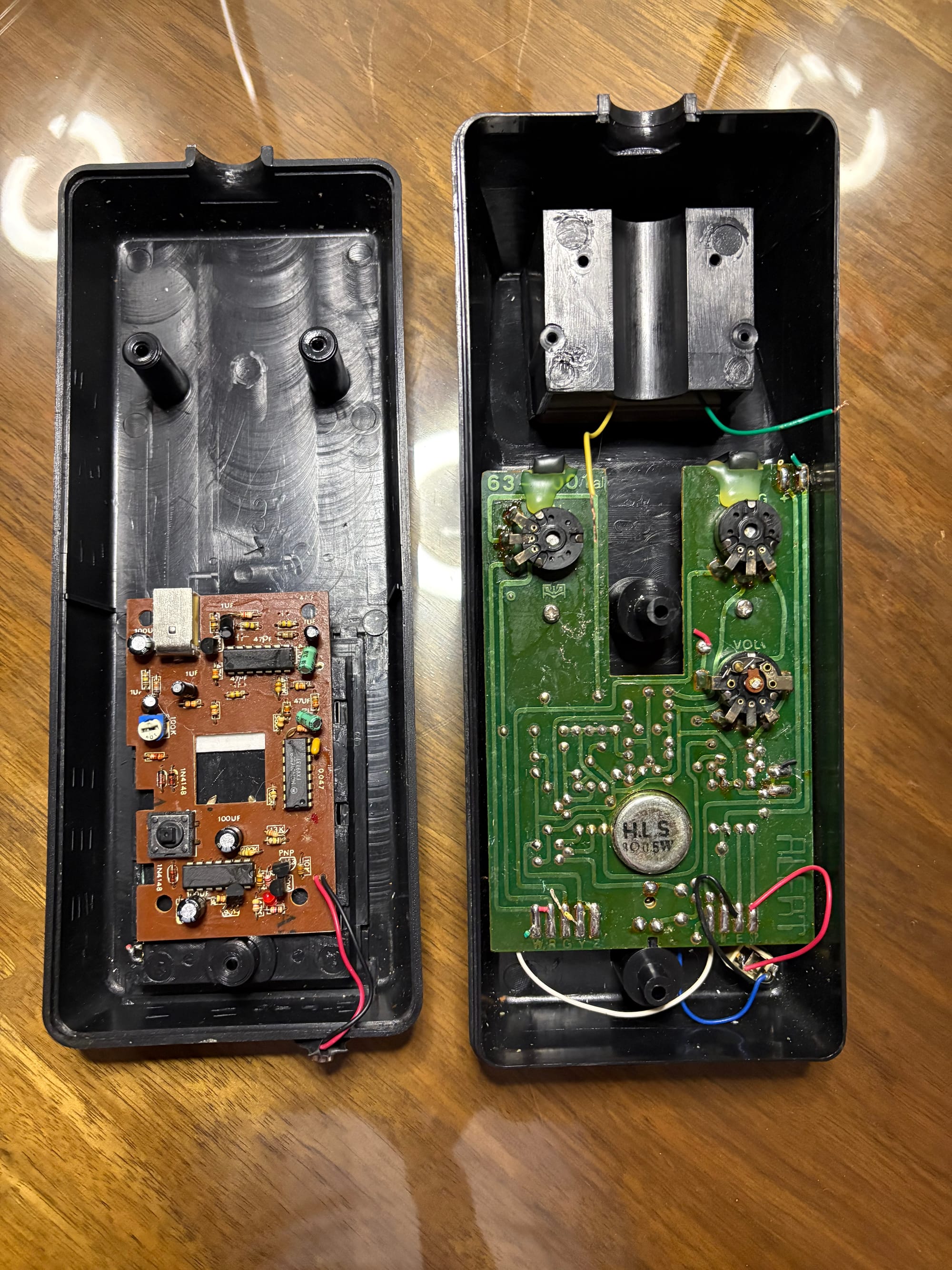
Assemble the Electronics
Okay, get your soldering iron ready and grab some heat-shrink tubing. We’re going to snip some wires, slide them into the heat-shrink tubes, solder them together, and then heat-seal them. Lay the EMF detector board across the battery compartment bump; later we’ll keep it here with some double-sided tape. First, connect the Micronata readout to the EMF detector. To do that, take the yellow wire from that screen and extend it to reach the right connector where you removed the screen from the EMF detector. Then extend the green wire to the left side.
For the battery, snip those two wires and extend them through the gap in the battery compartment. Then solder the connector pad back onto the red and black wires. A 9V will fit in this compartment; it's a tight fit, but it will work. So, no more work there.
The speaker is a small metal puck that vibrates against metal layers to make squeaks and squeals. Just extend those red and black wires so you can tape the puck against the bottom of the casing, toward the top.
I didn't take a photo of the red LED connection, but you’ll want to connect it to the bottom of the board. Do what I did: hook up your 9V and power on the EMF detector, then, while it's flipped over, find the connections for the currently installed LED and test which two power your new LED. It's essentially one directly under it and one slightly off to the right. Mark them, then run two really long wires of different colors that can go through the case and reach the top with some slack. You can always cut them when we solder the LED toward the end of this build, but you don’t want to add more. You could also try snipping it off the top, but mine was pretty tight, and I didn’t want to break a trace.
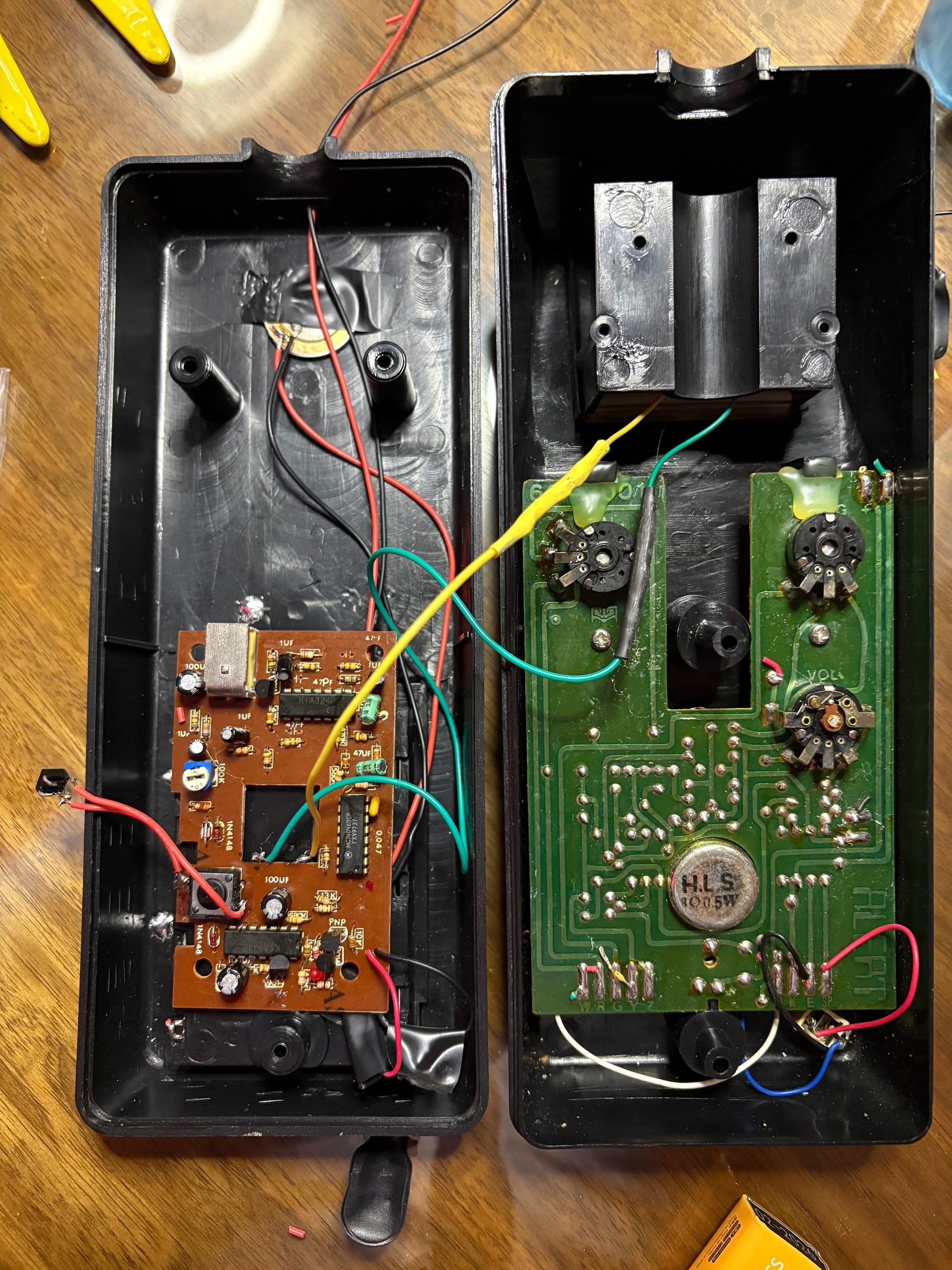
For your push button, attach a wire to the bottom right and top left of the original button on the EMF detector. Then, since these aren’t specifically labeled in any meaningful way, touch those two wires to the prongs on your new button and see if it comes on and does the room reading while depressed. Mine was two on the same side, but I can’t tell you for sure if that was the “right” side or “left.
For the LED wire, I drilled a hole in the center of the body in the bottom section. I believe the screen used prop was centered but on the top half. I wanted to make this easier to dismantle later in case something broke, so having more slack in those wires made sense to me, and I liked the idea of having a longer tube.
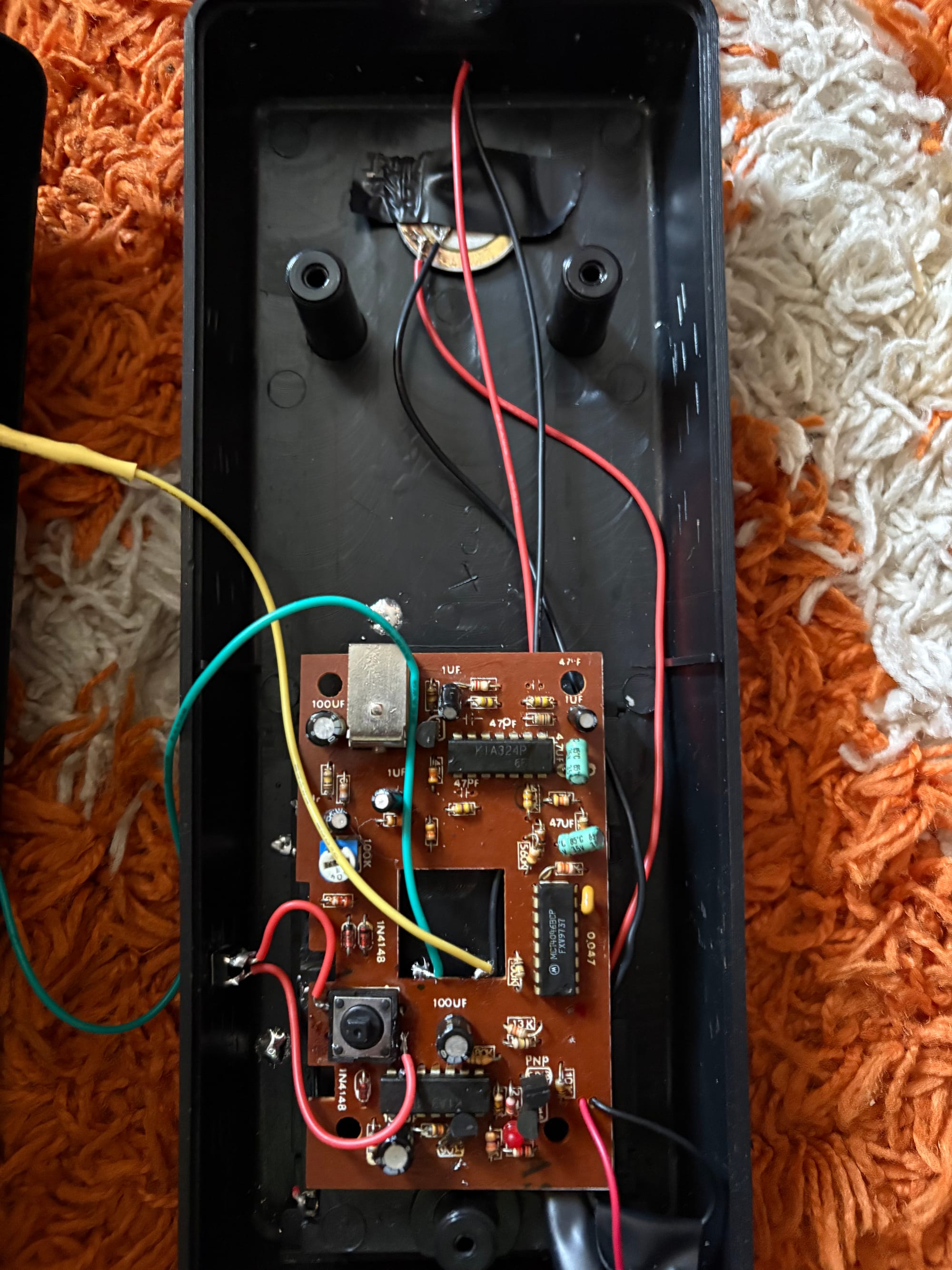
For the button, I ran it directly out the side because I wanted it to be discreet, and glued it to the inside plastic. Unfortunately, my button was a bit small/short; I couldn’t depress it easily, and I had to add another small piece of plastic.
That is essentially it for the electronics! Once we mount the masher, we’ll need to solder the LED, but that is it. Now that wasn’t such a chore, now was it?
Dry run of the electronics
Masher and Strainer
I took my own route on attaching the masher and strainer. I believe the screen used prop has the masher cut and stuck directly into the top shell. The strainer is cut short and stuck upright through the metal pole. I decided to keep the masher completely on the outside and attach it with a bend, and stick the strainer into the pole and bend it as well.
First, we need to cut the pole. I opted to use the small slit on the outside end as part of the strainer mount, where an M8 hex can fit. You also can’t use the internal center post that holds the pole in place if you add the EMF board, so we’ll cut from that side. I don’t think anyone has a screen-accurate measurement of how close the strainer and masher are, so you can dry fit it to your liking. Mine sit about an inch and a half (1 1/2") apart, so to match that you’ll want your pole about 10 inches long.
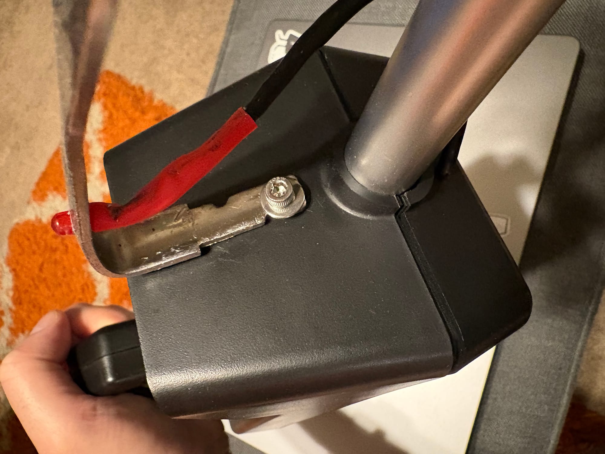
For the masher, there is already a hole drilled in it, so I clamped it to my workbench and bent it to match the slope of the Micronata shell. Then I used an M8 hex screw to attach it with a nut on the inside, which felt very appropriate for a Ghostbusters prop since they use those all over the proton pack. Before you attach it, drill out one hole in that arm so you can drop your LED in there.
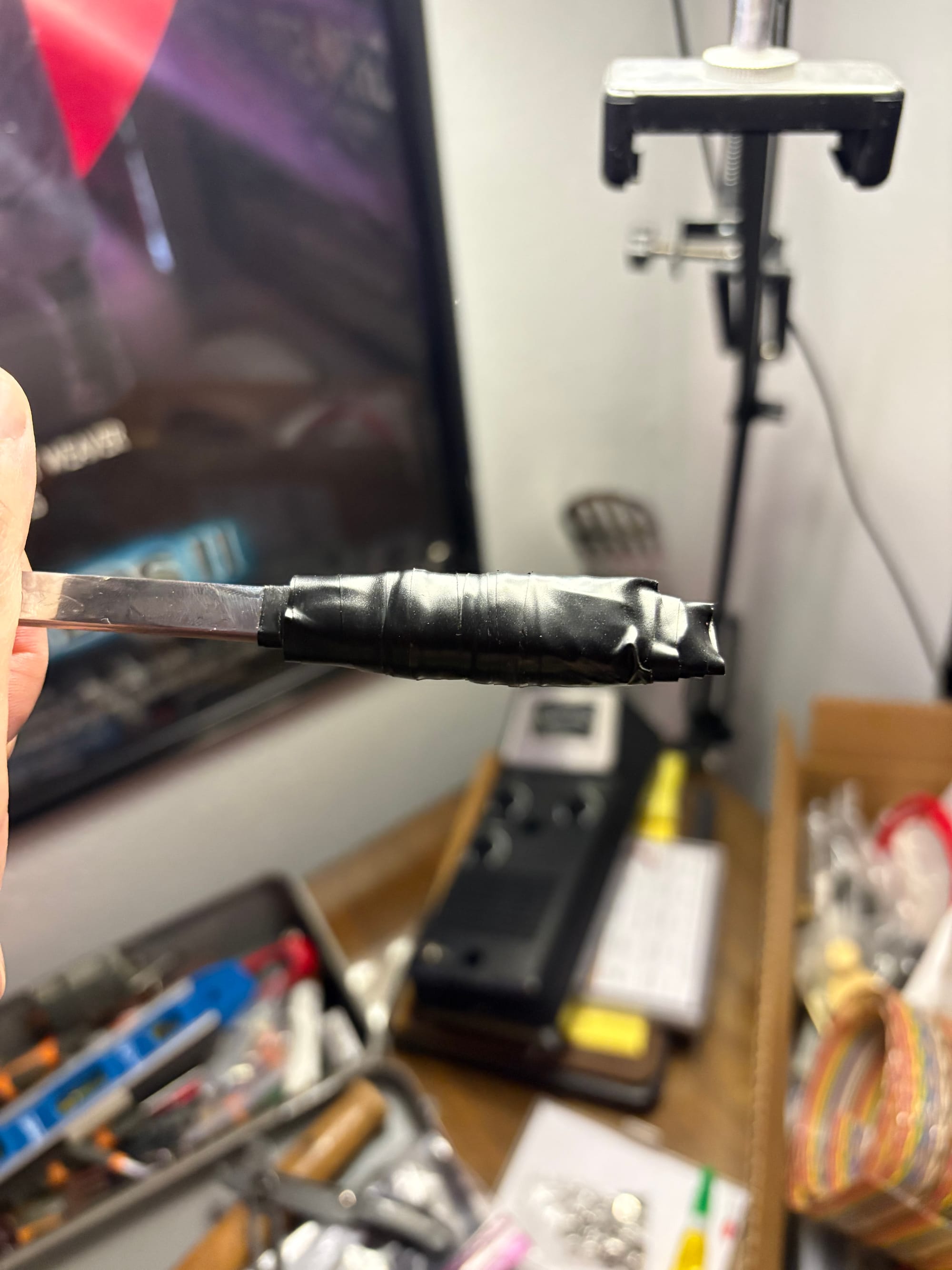
For the strainer, I cut off the wider part of my handle that wouldn’t fit inside the pole from the Micronata. Then I wrapped that handle in electrical tape so it fit snugly down inside the pole. The strainer bends very easily, so once I pushed it all the way down, I bent it by hand to face the masher.
If I were to change anything on this build, I would leave a little extra at the end to give that bend a little more height so it aligned dead center with the masher—something to consider.
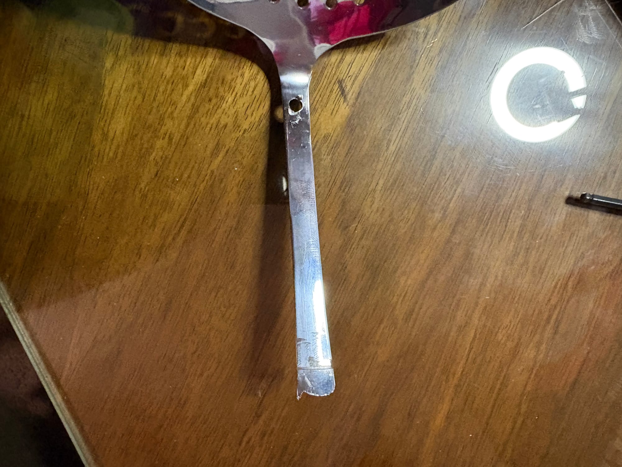
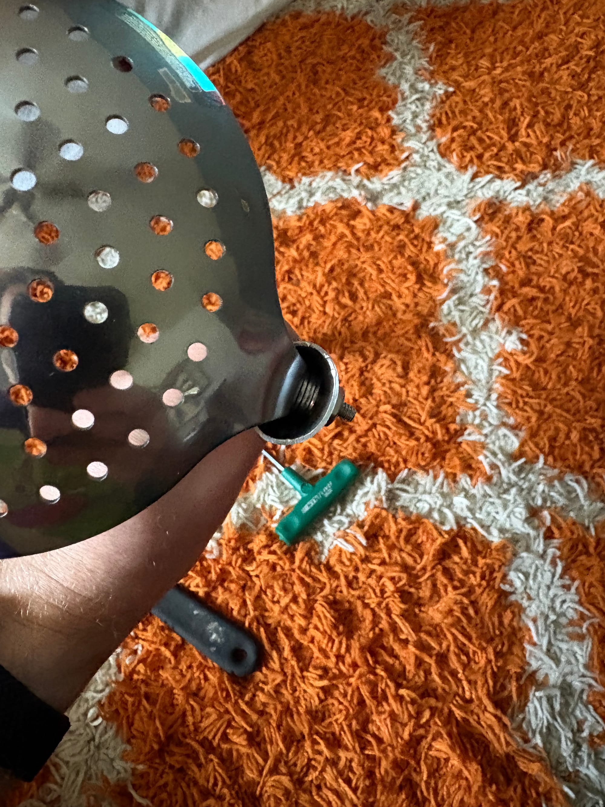
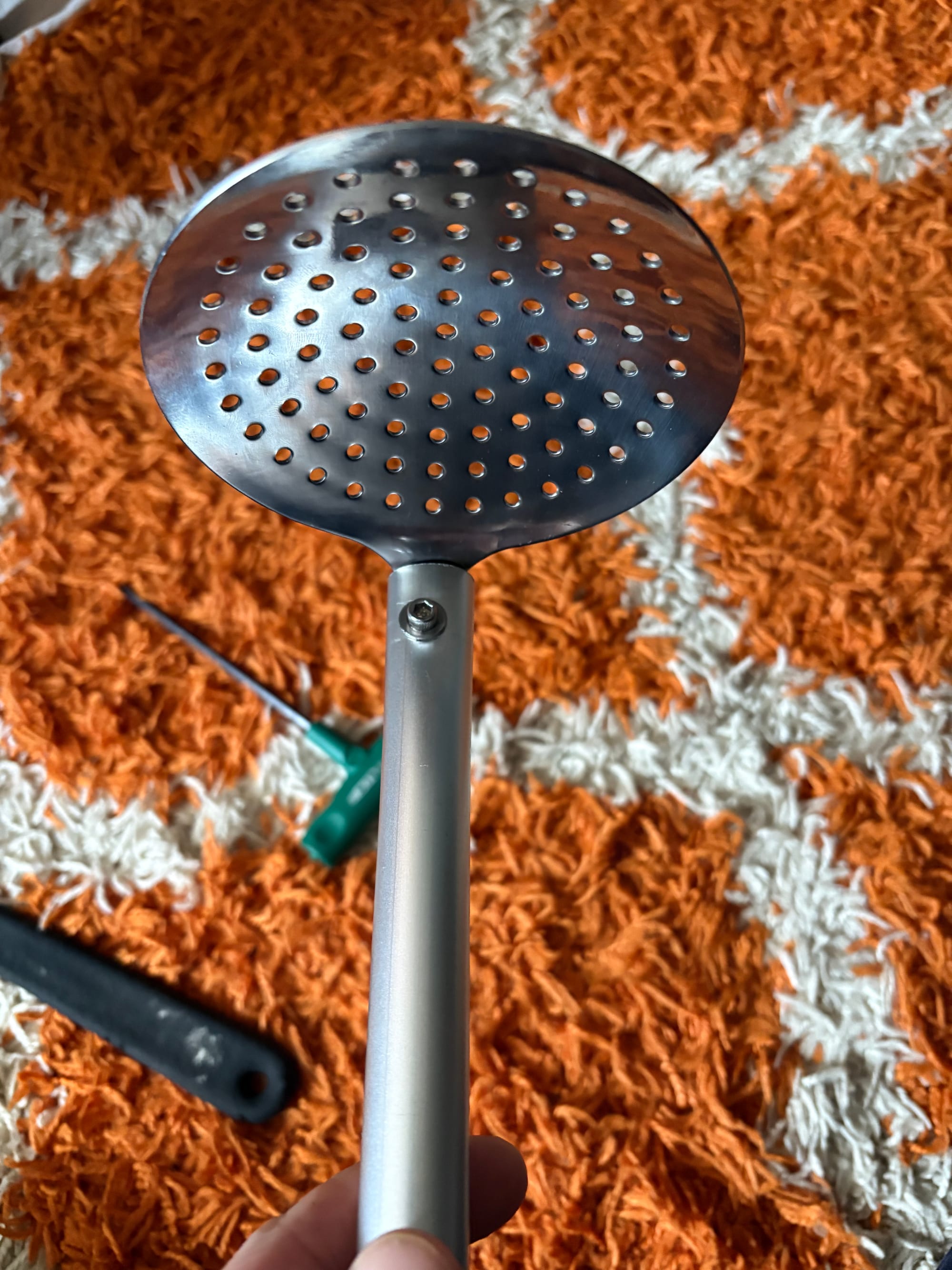
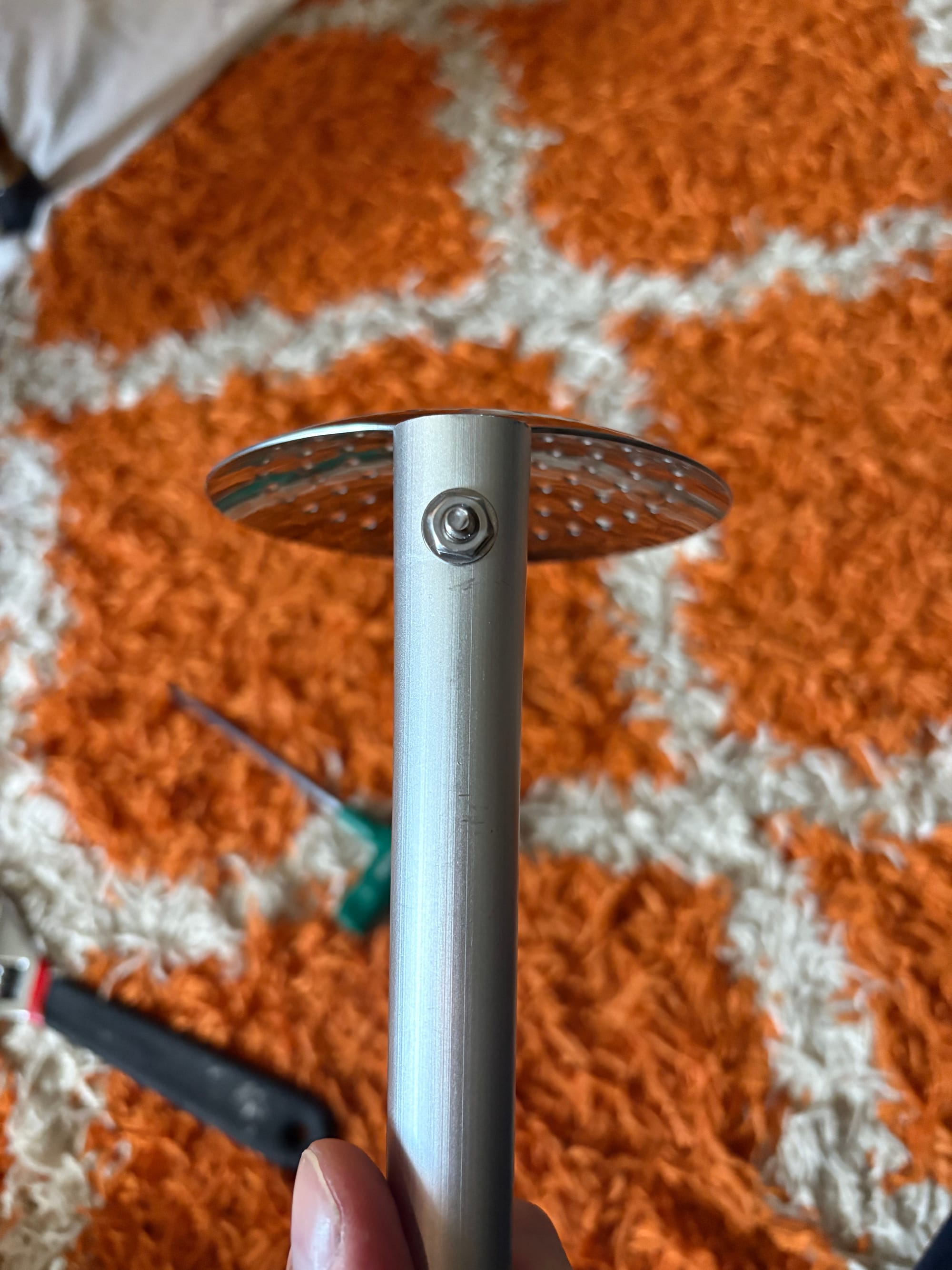
Once you have the bend where you want it, mark where the slit is in the handle and remove it. Now drill a hole through the handle to fit an M8 hex screw. Slide it back in and line up the screw through a washer and through the hole. Stack washers on both sides as you feed it through. You can also make spacers (rubber or otherwise) and use springs. I didn’t have any of these on hand, so I stacked washers on each side; this provides more tension so the strainer doesn’t wobble. On the other side, use a nut to hold it all in place and tighten it down as tight as it can go; I crimped together the pole a bit. If it's still a little loose drop a bit of glue (super or hot) between the strainer and the washers.
Put it back together and finish it up.
Okay, we can now reassemble it and finish a few final things.
Slide the pole in and attach it with the original bracket. It will still slide a bit since we aren’t using that post, so if you're worried, add a few drops of hot glue. Then screw the body and handle back together using the two long screws and two short. Remember, one of the handle screws stays inside.
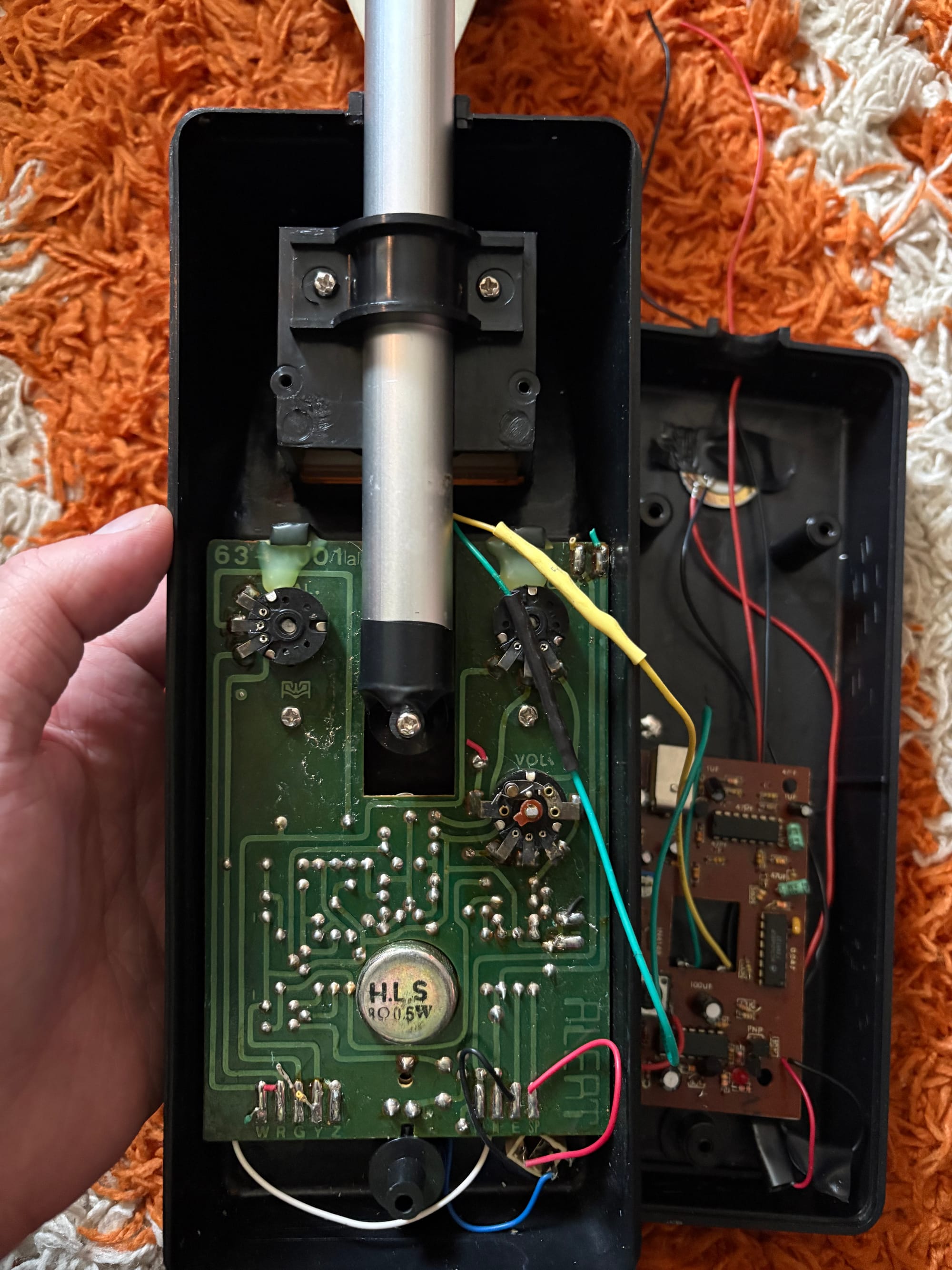
Almost there! Now drop your LED in the hole of the masher, and glue it in. Since we wired up the LED on vibes, turn on the EMF detector again and find out which wire connects to the long or short post to power the LED. Could we have been smarter and used a multimeter to find positive and negative, mark them accordingly, and then use the proper colored wires to start? Yes, but I didn’t have one handy, and as I mentioned, I did this whole thing in essentially an afternoon and felt it out as I went along. Anyway, slip some heat shrink over the wires, trim and solder them on, and then heat it to make it look nice.
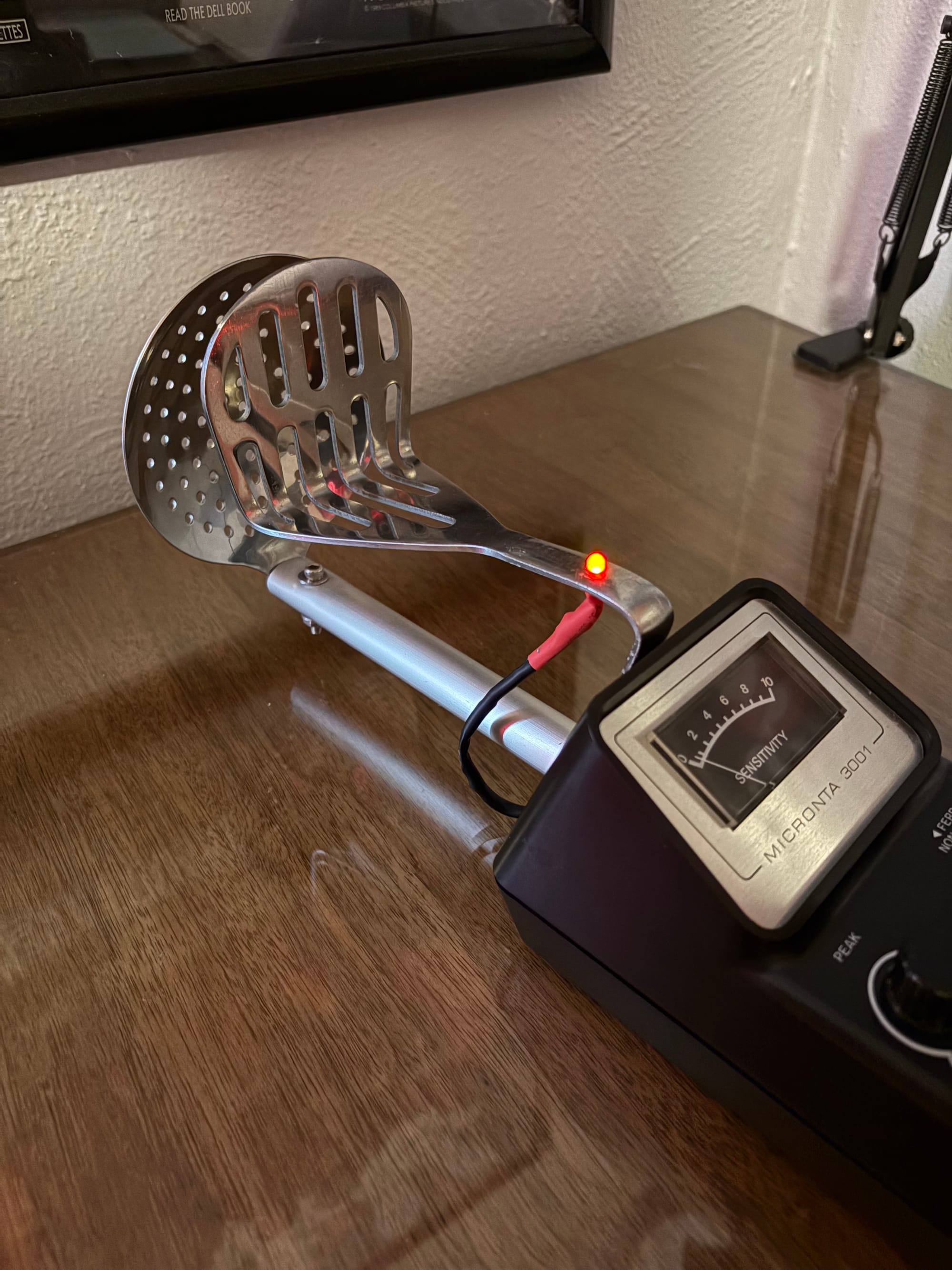
We’re done!
You should now have a functioning KUD Meter! Fully assembled, and when you switch it on, you can walk around and “detect ghosts” using the built-in EMF detector, with an LED that should stay on until the unit auto-shuts off. Since we didn’t reconfigure the EMF board, it won’t be very sensitive, but watching the needle move and hearing the beeps really gives this mostly static prop that extra bit of flavor.
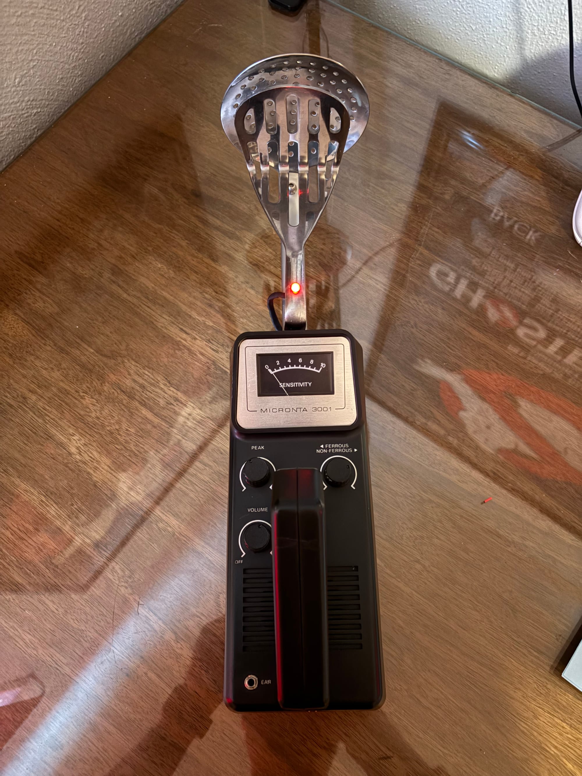
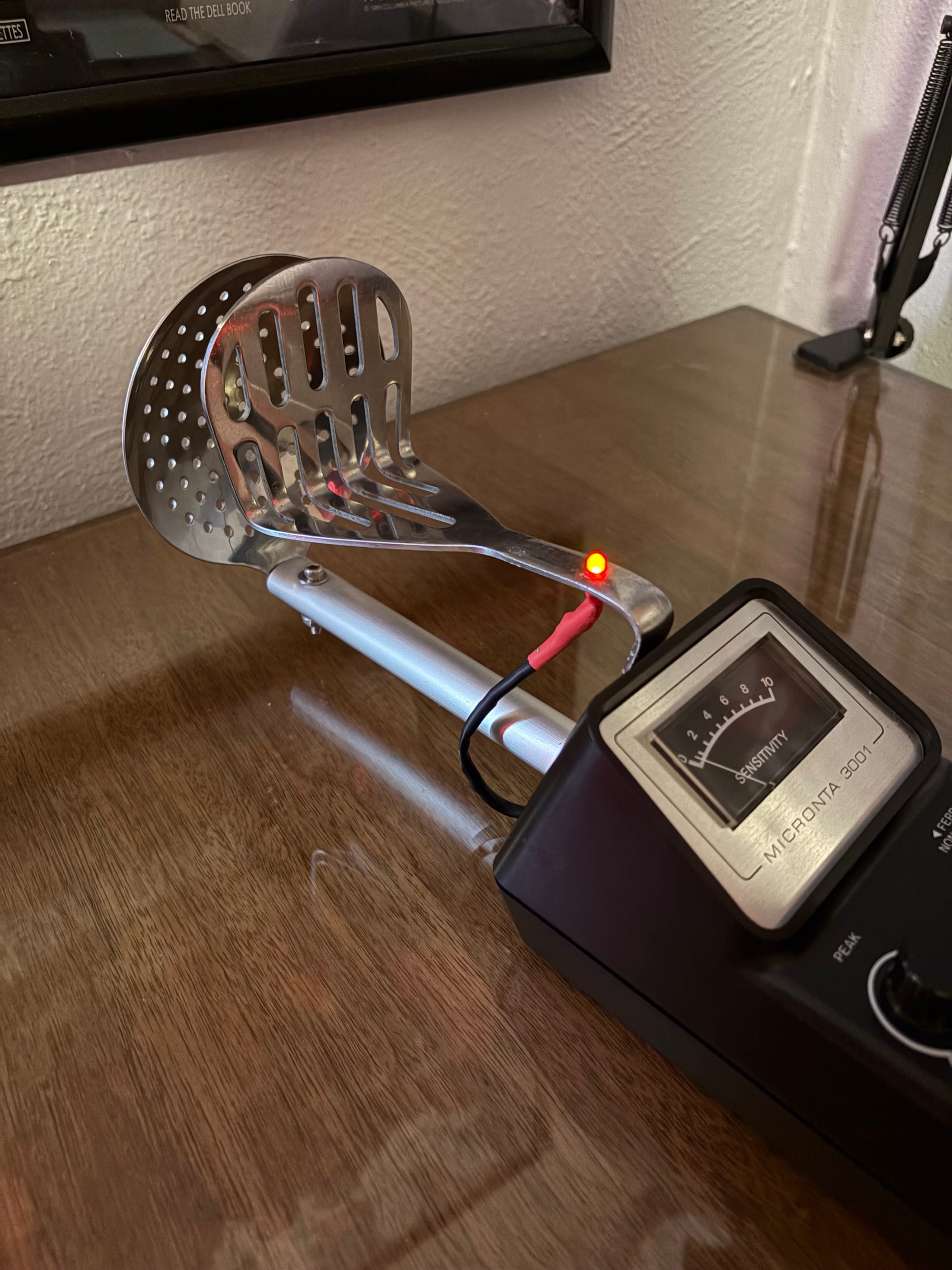
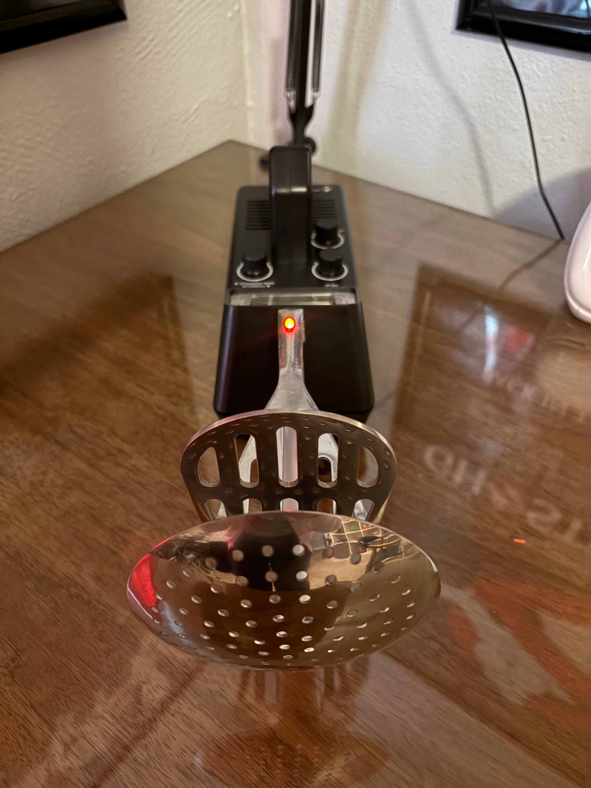
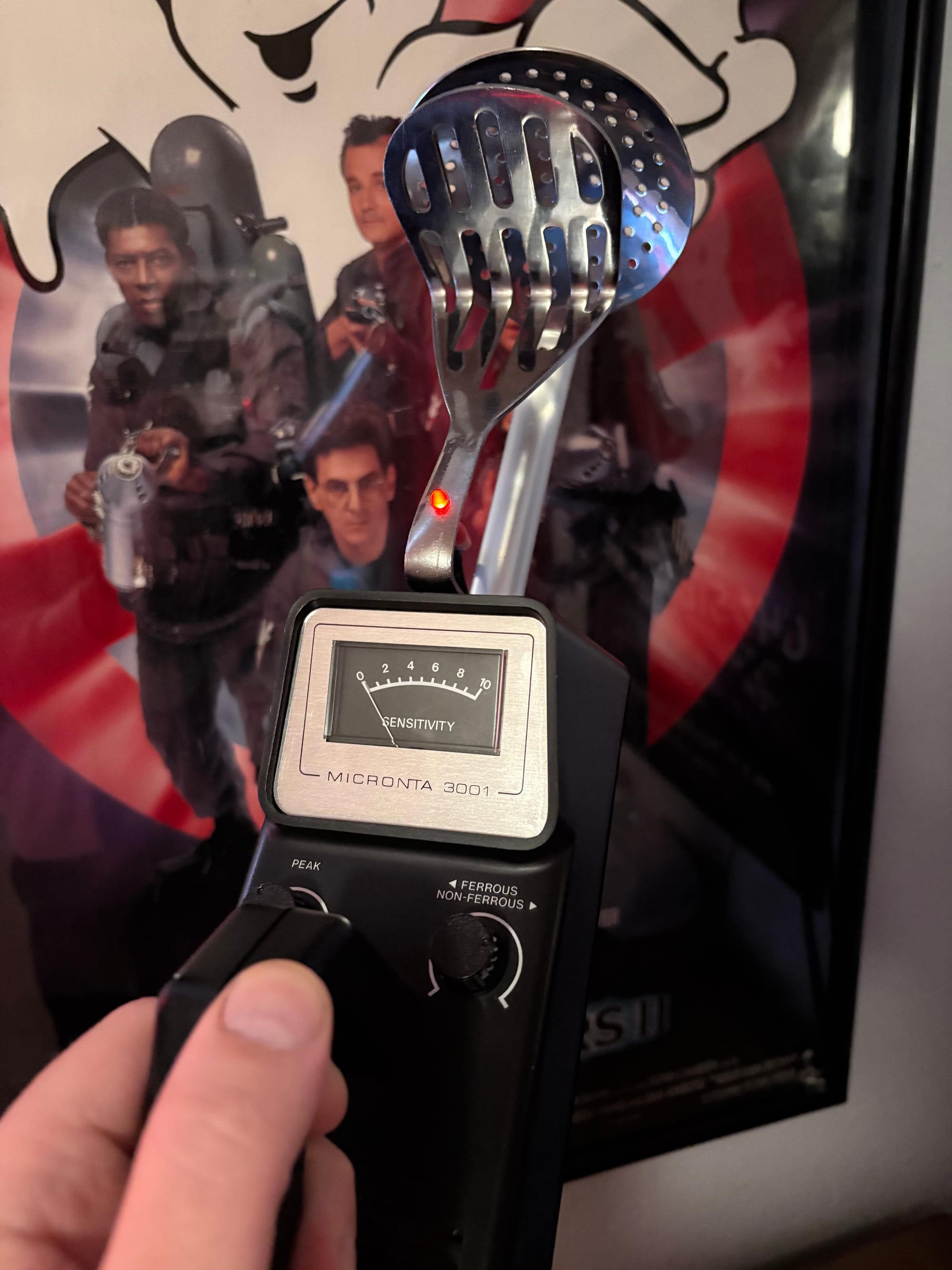
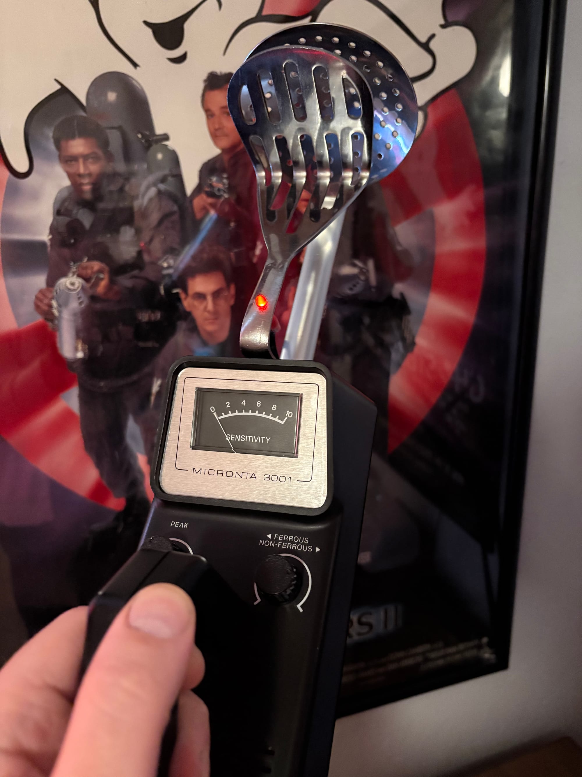
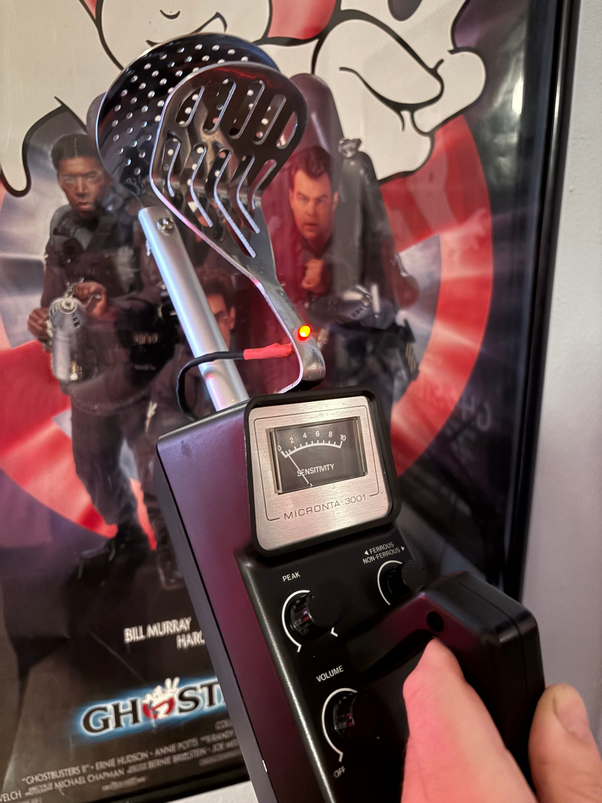
It isn’t a dazzling Ghostbusters prop, with lots of interesting sounds, moving parts and lights–we literally never see it do anything–and it isn’t even one that is seen for more than a couple scenes. Hell, I doubt anyone who isn't a very dedicated Ghostbusters II fan will even recognize it. But to me it's an awesome prop, even if only ever used as a shelf sitter. But if you ever do take it out, it should raise a few eyebrows, it is just weird enough.
See you next time fellow Busters!

Comments ()